Build, Analysis, Simulation
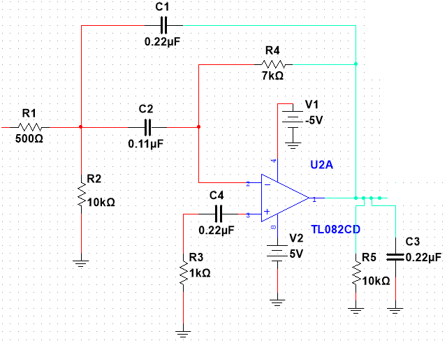
The bandpass filter used in the detection circuit was first simulated using the software Multisim in order to easily adjust the resistor and capacitor values to obtain the frequency range desired.

Figure 1: Schematic of modified, simulated bandpass filter in Multisim

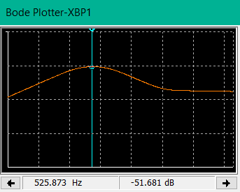
Figure 2: Bode plot depicting the bandpass filter with a frequency range of 400Hz-800Hz